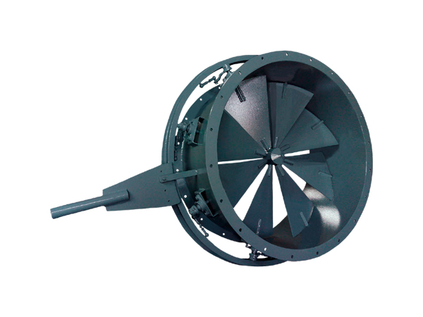
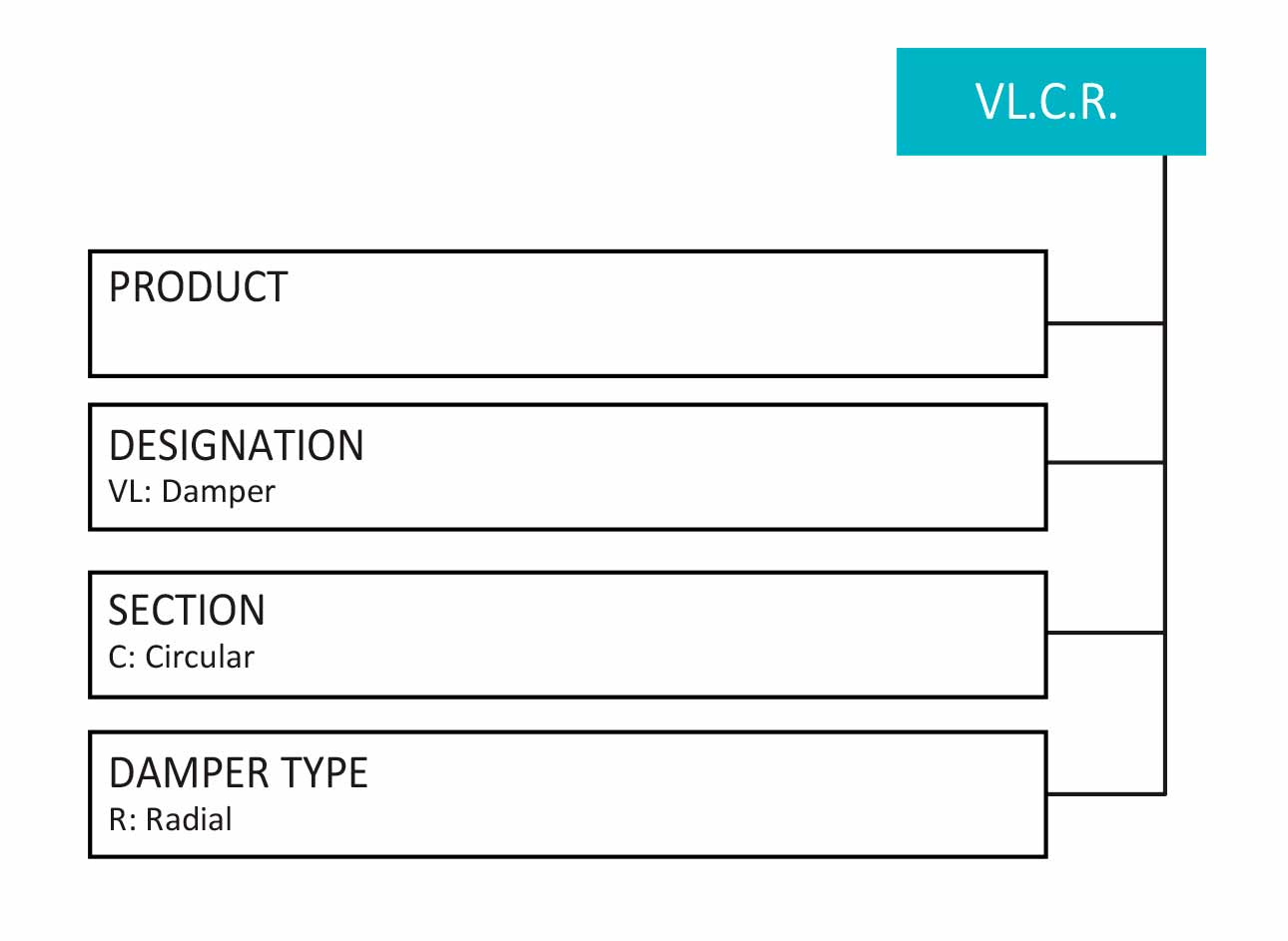
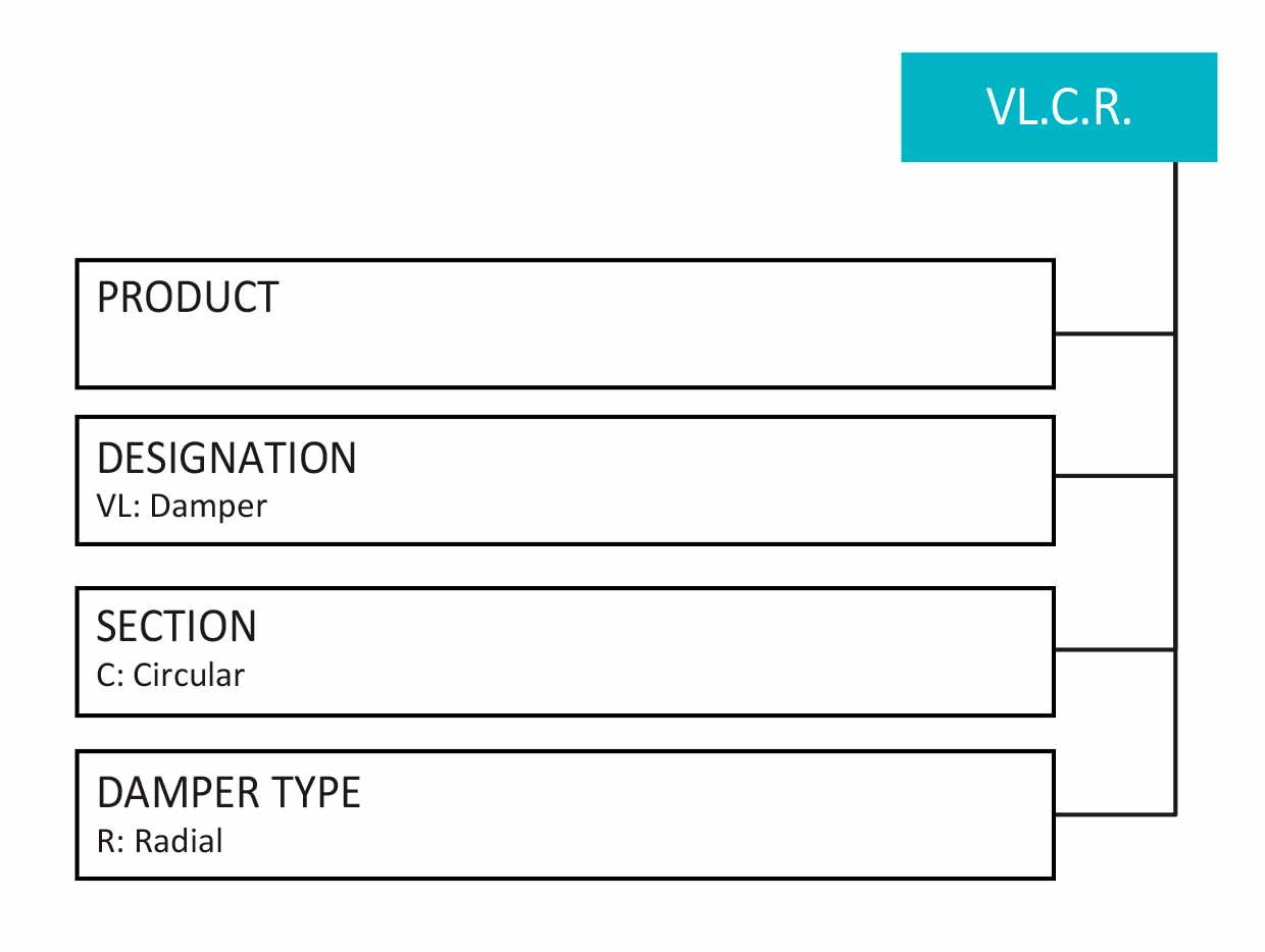
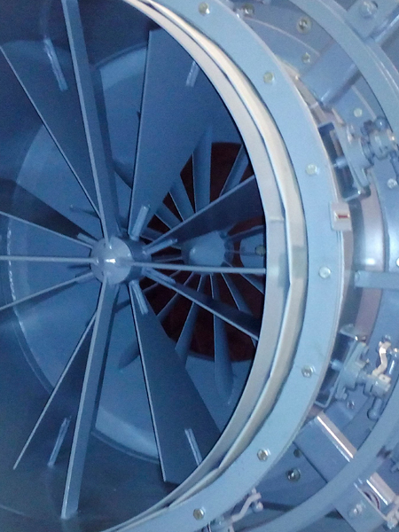
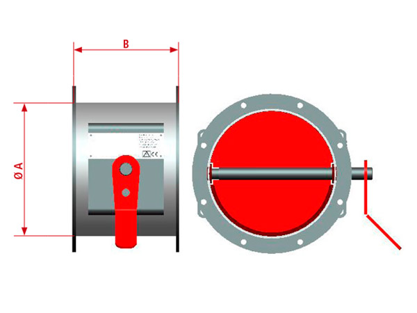


Radial “inlet-vanes” valves, also known as vortex dampers, are used in all types of installations for the regulation of flow and pressure in centrifugal fans.
They are designed to generate an inlet vortex in the same direction as that of the fan rotor (pre-rotation), causing a reduction in energy consumption, since the air flow is reduced, thus reducing the work done. That is, the relative speed between the fan and the inlet flow is reduced.
This type of flow control is most effective in conditions of reduced performance for a long period of time, or also, when the system requires regulation during operation. As a consequence, the operating characteristics of the fan are altered and the probability of fan instability is reduced.
Using this type of valve produces an effect on the system that must be taken into account when designing a fan, respecting the requirements specified by the customer.
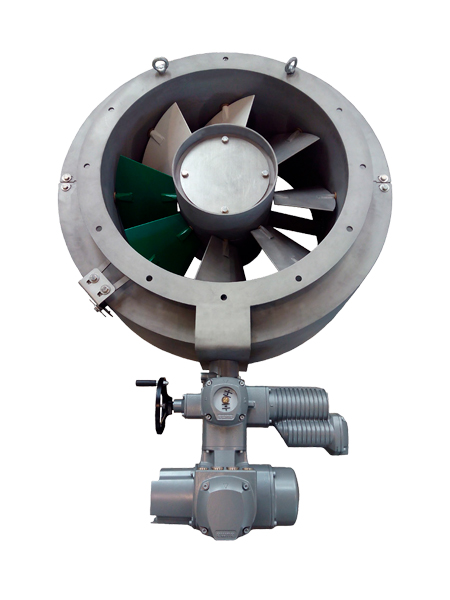
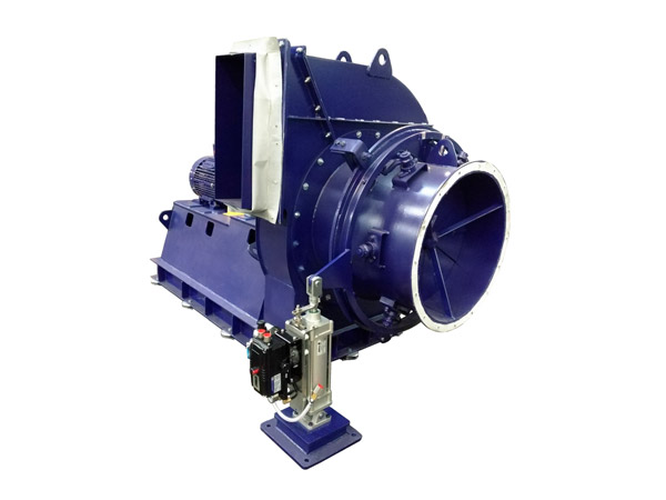
This valve is used in all types of applications where regulation is required. Its construction allows it to be used in extreme conditions, being able to withstand maximum pressures of up to 2.5 bars and maximum working flow rates of up to 9 m 3 /s.
It is specially built to withstand saline and maritime environments, using the most appropriate materials in each case.
It has open and closed positions, but this valve has a full 180º stroke for special applications that require it. It also has intermediate positions, adjusting to the needs of the client or the installation.
This valve has the ability to close in any direction and is designed so that it can work with flow in both directions.
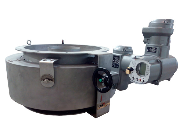
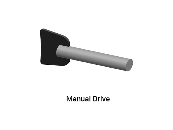
This valve can be actuated by a pneumatic, hydraulic or electric actuator. If required, you can also have a manual override, for emergency cases, that is complementary to those mentioned above.
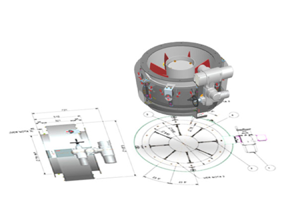
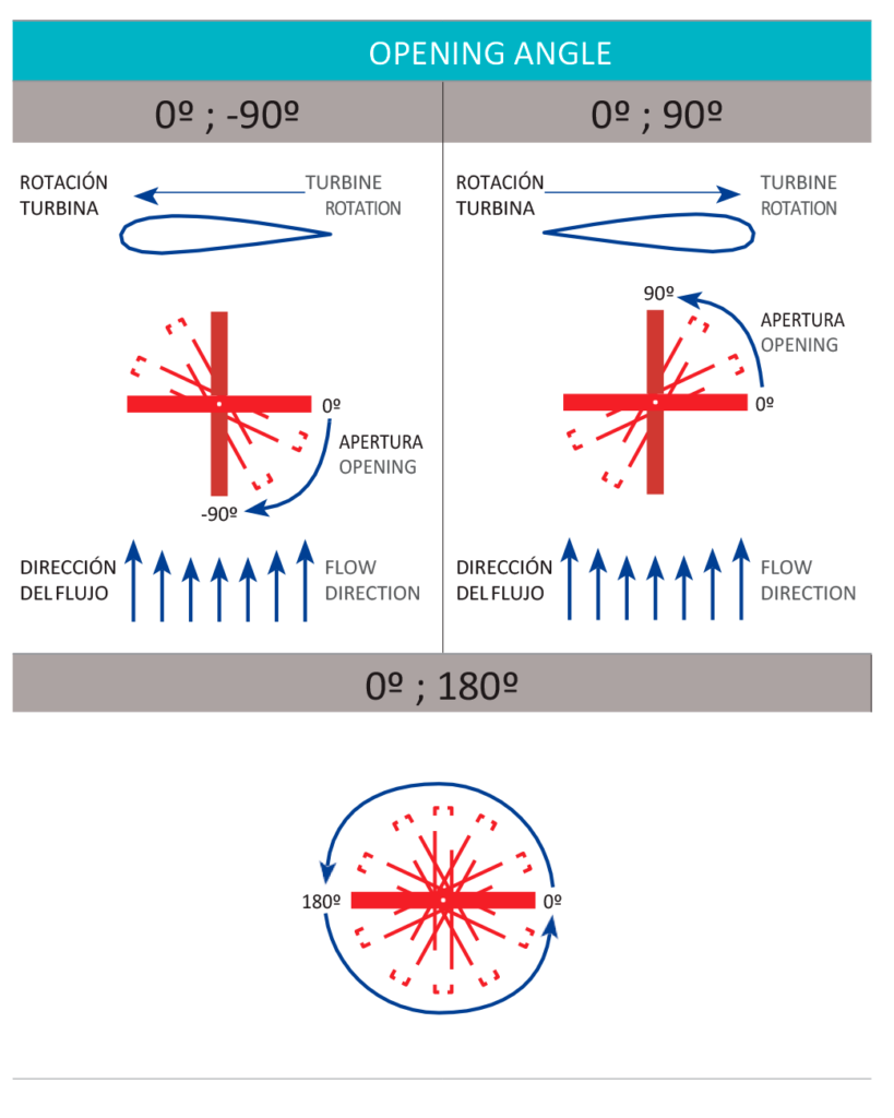
Being on request, this valve adjusts perfectly to the needs of the client, being able to customize the material, the number of blades, dimensions, etc. Depending on the application or the direction of rotation of the turbine, it will also be possible to customize the angle of opening and closing of the valve, which can be 0º; -90 °, 0 °; 90º or 0º; 180º (Special Execution).
This damper can be triggered using a pneumatic, hydraulic or electric actuator. If it is required it can be triggered using a manual drive, in case of emergency, which is complementary to the aforementioned.
As these dampers are under request, they adjusts perfectly to the customer needs, being able to personalize the material, number of blades, dimensions, etc. Depending on the application or on the turbine rotation way, it will also be possible to personalize the opening and closing angle, being possible 0º; -90 °, 0 °; 90º or 0º; 180º (Special Execution).
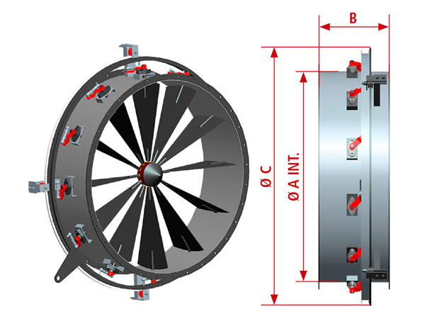
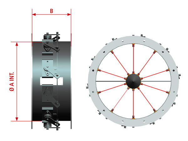
| Ø A (mm) | B (mm) | Ø C (mm) | PESO (Kg) |
|---|---|---|---|
| 250 | 180 | 550 | 19 |
| 280 | 200 | 580 | 21 |
| 300 | 210 | 600 | 25 |
| 340 | 240 | 640 | 31 |
| 380 | 270 | 680 | 44 |
| 410 | 290 | 710 | 63 |
| 440 | 340 | 1040 | 94 |
| 480 | 350 | 1080 | 100 |
| 520 | 380 | 1120 | 113 |
| 580 | 400 | 1180 | 119 |
| 620 | 410 | 1220 | 125 |
| 680 | 460 | 1280 | 144 |
| 740 | 400 | 1340 | 156 |
| 820 | 460 | 1420 | 188 |
| 900 | 460 | 1500 | 200 |
| 980 | 490 | 1580 | 213 |
| 1070 | 460 | 1670 | 250 |
| 1150 | 490 | 1750 | 300 |
| 1280 | 530 | 1880 | 338 |
| 1390 | 540 | 1990 | 375 |
| 1530 | 540 | 2130 | 413 |
| 1700 | 550 | 2300 | 488 |
| 1850 | 550 | 2450 | 538 |
| 2030 | 550 | 2630 | 875 |
| Ø A (mm) | B (mm) | PESO (Kg) |
|---|---|---|
| 250 | 180 | 12 |
| 260 | 180 | 13 |
| 270 | 180 | 14 |
| 280 | 200 | 15 |
| 290 | 200 | 17 |
| 300 | 210 | 20 |
| 310 | 210 | 21 |
| 320 | 210 | 22 |
| 330 | 210 | 23 |
| 340 | 240 | 25 |
| 350 | 240 | 28 |
| 360 | 240 | 30 |
| 370 | 240 | 32 |
| 380 | 270 | 34 |
| 390 | 270 | 38 |
| 400 | 270 | 40 |
| 410 | 290 | 53 |
| 420 | 290 | 55 |
| 430 | 290 | 65 |
| 440 | 340 | 74 |
| 450 | 340 | 85 |
| 460 | 340 | 85 |
| 470 | 340 | 87 |
| 480 | 350 | 90 |
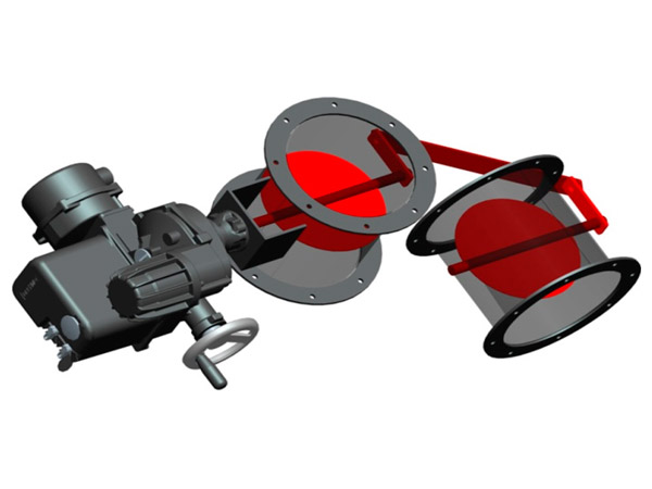
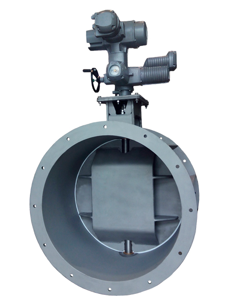
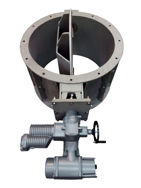
Butterfly valves are normally associated with flow control in ducts, but there are numerous applications in which they are used successfully in the inlet or intake of industrial fans due to their versatility and great ability to adapt to various sizes, pressures, temperatures, etc.
The different designs of this valve allow it to be adapted to the tightness required by the customer, thus making it totally hermetic or allowing the passage of air even when closed. There is not only the possibility of having the valve open or closed, but also in different intermediate positions.
Thanks to their personalized design and the use of the most appropriate materials, these valves are adjusted to the final working conditions depending on the needs of the installation, high temperature, corrosivity, etc.
These valves can be operated by all types of actuators; manual, electric, pneumatic and hydraulic. There is also the option of implementing special regulation systems under customer specification.
Subject to technical modifications.
| Ø A (mm) | B (mm) | PESO (Kg) |
|---|---|---|
| 250 | 250 | 16 |
| 280 | 280 | 18 |
| 300 | 300 | 22 |
| 340 | 340 | 27 |
| 380 | 380 | 38 |
| 410 | 410 | 54 |
| 440 | 440 | 81 |
| 480 | 480 | 86 |
| 520 | 520 | 97 |
| 580 | 580 | 103 |
| 620 | 620 | 108 |
| 680 | 680 | 124 |
| 740 | 740 | 135 |
| 820 | 820 | 162 |
| 900 | 900 | 173 |
| 980 | 980 | 184 |
| 1070 | 1070 | 216 |
| 1150 | 1150 | 259 |
| 1280 | 1280 | 292 |
Other measures on request.
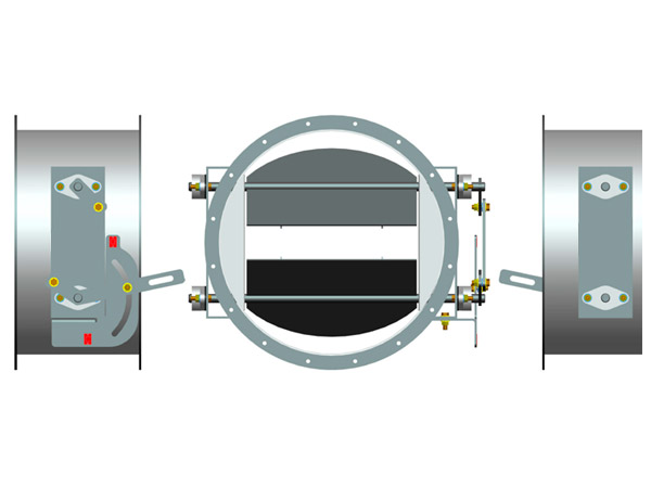
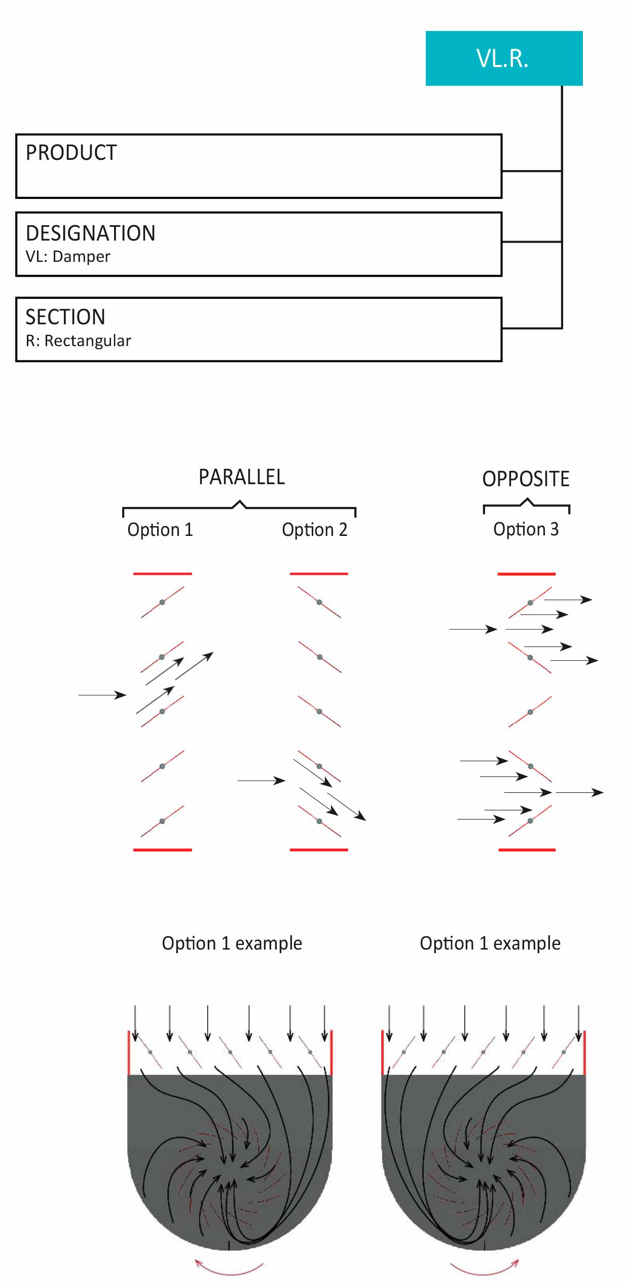
Opposing vane valves are made up of several vanes that each rotate on its own axis. Thanks to the mechanism that joins them, the slats rotate at the same time in opposite directions from each other.
Opposing louvers are best suited for maintaining a uniform air flow distribution immediately after the valve.
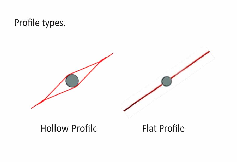
Depending on the client’s needs, the blades may be flat or hollow (airfoil profile). The flat profiles are reinforced so that they are sufficiently rigid without significantly affecting the load losses. The airfoil type profiles are reinforced on the inside and are not in contact with the fluid.
Thanks to their personalized design and the use of the most appropriate materials, these valves are adjusted to the final working conditions depending on the needs of the installation, high temperature, corrosivity, etc.
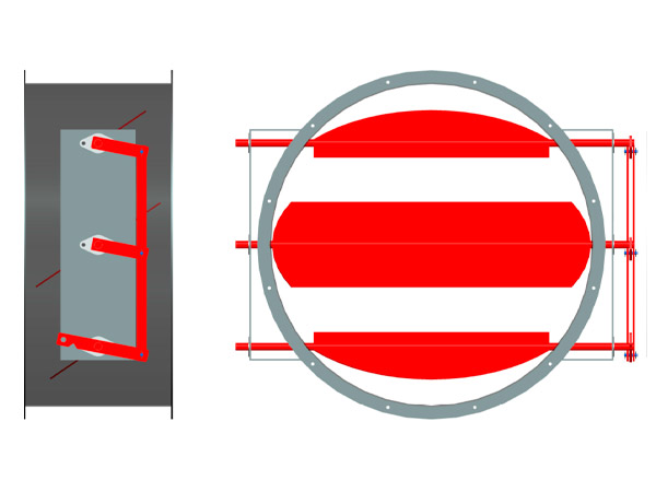
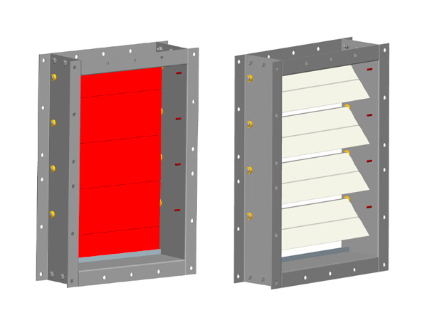
Parallel vane valves are made up of several vanes that each rotate on its own axis. Thanks to the mechanism that joins them, the slats rotate at the same time in a parallel way.
This type of valve with parallel blades is suitable when the valve is located in the suction box of a fan. The opening and closing of the slats depend on the direction of rotation of the rotor.
Depending on the client’s needs, the blades may be flat or hollow (airfoil profile). The flat profiles are reinforced so that they are sufficiently rigid, without significantly affecting the load losses. The airfoil type profiles are reinforced on the inside and are not in contact with the fluid.
Thanks to their personalized design and the use of the most appropriate materials, these valves are adjusted to the final working conditions depending on the needs of the installation, high temperature, corrosivity, etc.
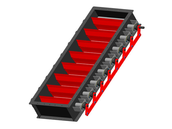
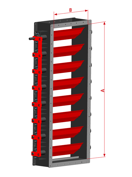
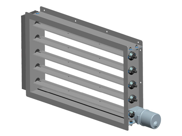
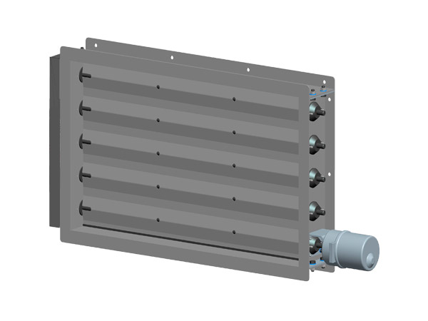
This model of regulation valve is a control system that can be installed in the suction box of a fan, so that it favors the entry of air. It can also be installed in the drive part of a fan or in any other part of the installation where it is necessary or required by the customer.
Its efficiency stands out in conditions of reduced performance for a long period of time, as well as when during operation, the system requires regulation.
In rectangular valves, the blades are positioned parallel to the axis of the fan, and move uniformly thanks to the joint system between them. When we keep the slats partially closed, a vortex is generated inside the suction box that rotates in the same direction as the rotor.
This effect is similar to the radial valve.
Thanks to their personalized design and the use of the most appropriate materials, these valves are adjusted to the final working conditions depending on the needs of the installation, high temperature, corrosivity, etc.
Non-return valves, also known as check valves or one-way valves, have the function of allowing air to flow in only one direction. To do this, thanks to its mechanism, the slats close automatically when the air tries to go in the opposite direction. They are used whenever there is a risk of backflow.
In these valves, the shaft is located at the top of the slats, rather than in the center. In this way, the slats fall due to gravity and their own weight, and will only allow air to pass in one direction.
Although the mechanism is very simple, its function is very important, since it avoids the counter flow of toxic / contaminated air that can exist in certain situations.
Thanks to their personalized design and the use of the most appropriate materials, these valves are adjusted to the final working conditions depending on the needs of the installation, high temperature, corrosivity, etc.
The regulation gates or control windows have the function of closing their slats in case of emergency. This is done in order to avoid the escape of fumes or gases to the outside or adjoining rooms.
These slats have two positions, open or closed. In both positions, the supply includes limit switches, making it possible for the motor to remain in a resting state without having to maintain the motor’s electrical activation voltage.
Thanks to their personalized design and the use of the most appropriate materials, these windows or valves are adjusted according to the installation conditions and the available equipment. You can also configure the opening or closing range of the slats in intermediate positions depending on the required application. Air temperature, corrosiveness, tightness, etc. are factors to take into account.
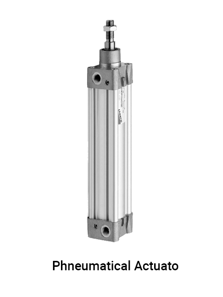
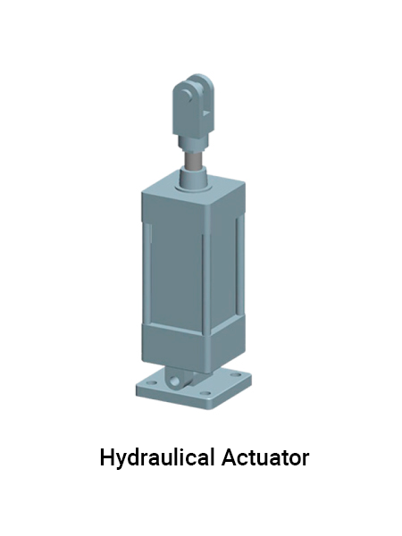
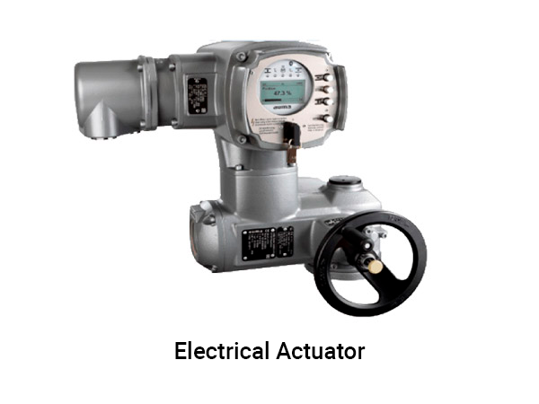
Actuators are devices that are responsible for generating an effect on an automated process thanks to the transformation of energy, whether electrical, pneumatic or hydraulic, in the activation of a process.
The valves can be operated by the following actuators:
• Electrical
• Tires
• Hydraulic
The possibility of complementing these actuators with a manual one is always offered. This will help in situations of need. There is also the option of implementing special regulation systems under customer specification.